OSCADY PRO Original/Final Sequences - TRL Software
01344 379777software@trl.co.uk
TwitterYouTubeLinkedin
  • TRL Main Site
  • Careers
  • Publications
Top Menu
Search
Cart0
  • No products in the cart.

Subtotal: £0

View Cart Checkout

TRL SoftwareTRL Software
TRL Software
World Class Traffic & Transportation Software Solutions
  • Products
    • Junction & Signal Design
      • Junctions
        • ARCADY
        • PICADY
        • OSCADY
      • PCMOVA
      • TRANSYT
    • Traffic Control
      • MOVA
      • SCOOT®
      • Urban Traffic Control (UTC)
      • MotorGraph
    • Road Safety
      • iMAAP
      • Street Auditing
    • Economic Appraisal
      • HDM-4
    • Digital Asset Management
      • iROADS™
  • Services
    • Junction Analysis
    • Microsimulation Services
    • Signal Control
    • Road Danger Reduction
    • Software Development
    • Strategic Modelling
  • About
    • TRL Software
    • Quality Standards
    • Careers
  • News
  • Support
    • Training
    • Knowledge Base
    • Webinars
    • Videos
    • Support Options
    • Maintenance Agreement
    • Licensing
    • Online Store Help
    • Ideas Portal
    • FAQ
  • Contact
Menu back  
TRL Software > Support & Training > Articles > OSCADY PRO Original/Final Sequences

OSCADY PRO Original/Final Sequences

The original sequence column shows the ‘original’ stage sequence, either manually input or produced by the Sequence Generator. This may or may not bear much resemblance to the Final Sequence, which is what you see in final outputs and phase/stage timings. The original sequence can be considered as an ‘initial guess’, which the optimiser then refines and adjusts. (If you are forcing stages, however, the original and final sequences should match.) Generally, the final sequence is a subset of the initial sequence.
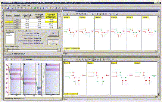

This is illustrated in the PHASE CONSTRAINTS screenshot example. For the active solution (Sequence 2, Minimum Delay), the original stage sequence was 1,4,5,6,3,2. This is shown in the upper Junction Diagram. (See the User Guide for details of how to set up the Junction Diagram to show stage sets. Note that the diagram shows its current mode in yellow at the foot of the diagram.) The final sequence, however, is 1,4,6,2, as shown in the phase timings diagram and in the lower sequence diagram; i.e. stages 5 and 3 have ‘dropped out’ of the solution. This is because the optimiser has found that they are not necessary for the optimised solution. For example, stage 5 represents a transition between stages 4 and 6 and so is ‘merged’ with the surrounding stages.

Of course, where you wish to force a stage sequence, and prevent any such merging, you can do so easily by entering a non-zero minimum green on the stage.

Categories
  • ARCADY Modelling
  • ARCADY/PICADY/OSCADY Technical
  • Other products
  • PICADY Modelling
  • TRANSYT Modelling
  • TRANSYT Network Diagrams
  • TRANSYT Technical
Recent Articles

  • TRANSYT 16 Simulation Model

  • Automatically calculating future traffic flows using growth factors

  • Graphs showing sensitivity of geometric parameters

  • How can I transfer traffic data between Junctions and Excel?

  • Pedestrian crossing and blocking on the same road

Stay up to date with news from TRL Software

Sign up
Products
  • Junction & Signal Design
  • Traffic Control
  • Road Safety
  • Economic Appraisal
  • Digital Asset Management
Services
  • Junction Analysis
  • Microsimulation Services
  • Signal Control
  • Road Danger Reduction
  • Software Development
  • Strategic Modelling
Contact Us

01344 379777
software@trl.co.uk

TRL Limited
Crowthorne House
Nine Mile Ride
Wokingham
Berkshire
RG40 3GA

TRL Software
TRL Registered Office: Crowthorne House, Nine Mile Ride, Wokingham, Berks, UK, RG40 3GA. Registered in England, No. 3142272, VAT Registration 664 625 321.
© Copyright 2021 TRL. All rights reserved.
  • Sitemap
  • Terms & Conditions
  • Privacy Notice
  • Accessibility
Footer Menu