Assessing inscribed circle diameter - TRL Software
01344 379777[email protected]
TwitterYouTubeLinkedin
  • TRL Main Site
  • Careers
  • Publications
Top Menu
Search
Cart0
  • No products in the cart.

Subtotal: £0

View Cart Checkout

TRL SoftwareTRL Software
TRL Software
World Class Traffic & Transportation Software Solutions
  • Products
    • Junction & Signal Design
      • Junctions
        • ARCADY
        • PICADY
        • OSCADY
      • PCMOVA
      • TRANSYT
    • Traffic Control
      • MOVA
      • SCOOT®
      • Urban Traffic Control (UTC)
      • MotorGraph
    • Road Safety
      • iMAAP
      • Street Auditing
    • Economic Appraisal
      • HDM-4
    • Digital Asset Management
      • iROADS™
  • Services
    • Junction Analysis
    • Microsimulation Services
    • Signal Control
    • Road Danger Reduction
    • Software Development
    • Strategic Modelling
  • About
    • TRL Software
    • Quality Standards
    • Careers
  • News
  • Support
    • Training
    • Knowledge Base
    • Webinars
    • Videos
    • Support Options
    • Maintenance Agreement
    • Licensing
    • Online Store Help
    • Ideas Portal
    • FAQ
  • Contact
Menu back  
TRL Software > Support & Training > Articles > Assessing inscribed circle diameter

Assessing inscribed circle diameter

It may be useful to bear in mind that the ICD is intended to represent the “size of the junction as perceived by an approaching driver”. This is admittedly an imprecise definition, which is why there is no set of precise rules to cover every set of circumstances, when the junction is not symmetrical in its design. But there are a few basic (and as precise as possible) guidelines:

1. Ignore lane-splitting or carriageway-dividing islands. Ignore any lane markings. These details do not have any bearing on the ICD. Delete them from your drawing if it makes it any easier to assess the size of your roundabout. If the roundabout is approximately circular there is no problem – use the measurement method described in the Application Guide. Similarly, if it’s oval there will be two ICDs, and each arm will be assigned to the smaller or larger of them.

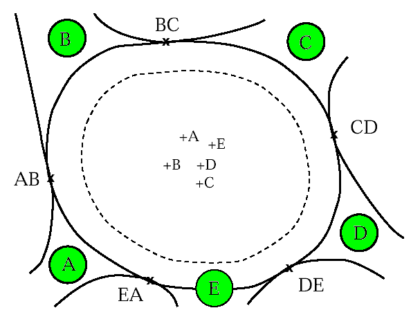
2. If the roundabout is a symmetric or unusual in some way, you will need to consider, for each arm, the “size of the junction as perceived by a driver arriving on that arm”. First, it is sometimes useful to use a flexicurve to draw around the outer perimeter of the junction, touching all the kerblines. You don’t need to be too pedantic about this process, because it’s only to give a guide. Examine your flexiline afterwards to see how well it reflects the overall size and shape of the junction – there is usually some trial and error before producing a line that looks “reasonable”. The figure shows this treatment applied to a five-arm large roundabout. Note that all islands and give-way lines have been deleted from the drawing.

Then draw circular curves for each arm, guided by the flexiline but entirely within it, centred somewhere on the central island. Each curve should encompass the arm in question, and should aim to touch the kerb at points closest to the centre of the junction on either side of the arm. For example, in the figure, the ICD for Arm B aims to pass through point AB and BC. Similarly, the ICD for Arm C aims to pass through points BC and CD … etc. The centres of these curves need not be at the same points on the central island – in the example shown you will see that they’re not. Often, it is not possible for a single radius curve to touch both points whilst remaining within the flexiline – you will need one radius to pass through one point, and another to pass through the other point. In this case, use the smaller radius as the ICD.

Finally, check that the comparative ICDs look correct. For example, in the figure, drivers approach on Arm E in an area where the radius of the junction is relatively large, whereas the radius is relatively small for drivers approaching on Arm D. So Arm E should have a larger ICD than Arm D.
Categories
  • TRANSYT Technical
  • ARCADY Modelling
  • ARCADY/PICADY/OSCADY Technical
  • Other products
  • PICADY Modelling
  • TRANSYT Modelling
  • TRANSYT Network Diagrams
Recent Articles

  • Script errors during login and password resets

  • TRANSYT 16 Simulation Model

  • Automatically calculating future traffic flows using growth factors

  • Graphs showing sensitivity of geometric parameters

  • How can I transfer traffic data between Junctions and Excel?

Stay up to date with news from TRL Software

Sign up
Search
Recent News
  • Modelling of intermittent stages in TRANSYT 16
  • Every journey starts with a walk – TRL & TfGM paper presented at the 2023 JCT Traffic Signals Symposium focusing on enabling Active Travel with UTC
  • RFC output in Lane Simulation Mode – Junctions 10
  • TRL Software Successfully Delivers New Pavement Management System for UK’s National Highways
  • We need you! Making our Software products work even harder for you….
News Archive
  • September 2023
  • July 2023
  • May 2023
  • March 2023
  • February 2023
  • January 2023
  • December 2022
  • November 2022
  • October 2022
  • September 2022
  • August 2022
  • July 2022
  • June 2022
  • April 2022
  • March 2022
  • February 2022
  • January 2022
  • August 2021
  • July 2021
  • May 2021
  • April 2021
  • March 2021
  • February 2021
  • January 2021
  • December 2020
  • November 2020
  • October 2020
  • September 2020
  • June 2020
  • March 2020
  • January 2020
  • December 2019
  • November 2019
  • May 2019
  • April 2019
  • September 2018
  • August 2018
  • October 2016
  • September 2016
  • February 2016
TRL Software
TRL Registered Office: Crowthorne House, Nine Mile Ride, Wokingham, Berks, UK, RG40 3GA. Registered in England, No. 3142272, VAT Registration 664 625 321.
© Copyright 2021 TRL. All rights reserved.
  • Sitemap
  • Terms & Conditions
  • Privacy Notice
  • Accessibility
Footer Menu