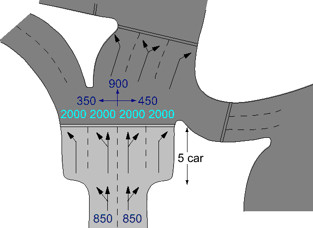
TRANSYT 16, 15, and 14: An alternative method can be used to model this kind of situation, by setting up explicitly the lane and traffic stream structure and using the “Flare” traffic model appropriately to represent the short bays that might block back.
TRANSYT 13 and earlier:
The diagram depicts an entry four-arm roundabout where the nearside lane splits into two: a bay for left-turners only, and the main lane catering for both straights and lefts. There are two objectives in modelling this stop line, which, as we shall see, conflict. Firstly the capacity of the approach requires that all traffic is modelled, which ideally requires the flare parameters to be specified in CT33. However, if variable saturation flow was modelled, arrival patterns on the down-stream link would be ‘nose heavy’. In reality, the down-stream arrival pattern would be constant because all left-turn traffic will have left the system, leaving straight-ahead traffic only to be modelled on the next link.

Modelling this uniform saturation flow correctly requires a single entry link on which the left-turners are ignored and the saturation flow is reduced by the proportion of the total traffic that travels straight-ahead (i.e. 500/850). Modelling the situation as described would be sufficient, unless left-turners either; (a) needed to be modelled further downstream, and/or (b) dominate the capacity of the approach.
In case (b) two TRANSYT runs would be required; the first would include the left turners, thereby deducing the green time required by that entry for capacity reasons; and the second would fix on that green time, and, by ignoring left-turners, calculate optimum offsets between junctions.
Also shown in the diagram is a situation where the main lane bays share common movement, as in the previous example. Unlike the previous example though, all the traffic in these lanes travels onto the next down-stream link; hence the variable saturation flow model will be required.
The difficulty here is that because the bay and main lane share the right-turn movement, right-turners can choose to queue in either. But, because the straight-ahead traffic is not free to choose, not only will the utilisation of the bay be under 100%, but it will also be unpredictable. In this example the bay is relatively short and a sensible guess at a utilisation figure would be acceptable (e.g. 3 per cycle). However, with longer bays, observed values ought to be used.