Where should you measure the approach width? - TRL Software
01344 379777software@trl.co.uk
TwitterYouTubeLinkedin
  • TRL Main Site
  • Careers
  • Publications
Top Menu
Search
Cart0
  • No products in the cart.

Subtotal: £0

View Cart Checkout

TRL SoftwareTRL Software
TRL Software
World Class Traffic & Transportation Software Solutions
  • Products
    • Junction & Signal Design
      • Junctions
        • ARCADY
        • PICADY
        • OSCADY
      • PCMOVA
      • TRANSYT
    • Traffic Control
      • MOVA
      • SCOOT®
      • Urban Traffic Control (UTC)
      • MotorGraph
    • Road Safety
      • iMAAP
      • Street Auditing
    • Economic Appraisal
      • HDM-4
    • Digital Asset Management
      • iROADS™
  • Services
    • Junction Analysis
    • Microsimulation Services
    • Signal Control
    • Road Danger Reduction
    • Software Development
    • Strategic Modelling
  • About
    • TRL Software
    • Quality Standards
    • Careers
  • News
  • Support
    • Training
    • Knowledge Base
    • Webinars
    • Videos
    • Support Options
    • Maintenance Agreement
    • Licensing
    • Online Store Help
    • Ideas Portal
    • FAQ
  • Contact
Menu back  
TRL Software > Support & Training > Articles > Where should you measure the approach width?

Where should you measure the approach width?

The ARCADY User Guide covers the “normal” 99 percent of roundabout approaches, where the approach width is measured just upstream of the point where local flaring begins, and therefore the approach is parallel-sided. The “width of the approach before the roundabout was built” is a convenient way of visualising the measurement required.

Sometimes, however, an approach might widen from (say) one lane to two lanes, at a significant distance upstream of the give-way line. The number of lanes is irrelevant, but the point is that the approach is parallel-sided from P1 to P2, and is also parallel-sided from P3 to P4.

Does the “local flaring” begin at P1 or at P3? Is the approach width equal to V1 or to V2? Would your answer be different if the two-lane section in the diagram was (say) 5 kilometres long rather than 20 metres long? Here is how to decide where to measure V in the real situations which will lie between these two extreme cases:
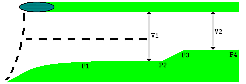

Run the model with V1 as your approach width. Check if:

(a) the mean queue on the approach is at all times contained well within the two lane section. Assume that 1 PCU plus the gap occupies 10 metres of queueing space – this is an overestimate, but it will allow for the random variability of queues.

(b) the capacity of the give-way line is not greater than the capacity of the link bottleneck at point P3 on the diagram. This is unlikely, because although the road at P3 is narrower than the give-way line, drivers at P3 are not having to stop and give-way. The capacity at P3 will simply be the saturation flow rate at that point. If the road at P3 is so narrow that the saturation flow at P3 is less than the roundabout give-way capacity, then V2 will be acting as the limiting factor and should be used as the approach width.

If both conditions (a) and (b) are met, then using V1 as the approach width is appropriate. Otherwise, you should use V2 as the approach width, and re-run the model. The queues from this 2nd run will probably be much bigger than in the first run, but this will be the correct model to use. N.B. Adjust flare details accordingly.

NOTE: in ARCADY 8 and above, you can use Entry Lane Analysis mode to explicitly set up this sort of lane configuration. You would set up two lane levels, with a zero (or minimal) flare in each lane level.

Categories
  • ARCADY Modelling
  • ARCADY/PICADY/OSCADY Technical
  • Other products
  • PICADY Modelling
  • TRANSYT Modelling
  • TRANSYT Network Diagrams
  • TRANSYT Technical
Recent Articles

  • TRANSYT 16 Simulation Model

  • Automatically calculating future traffic flows using growth factors

  • Graphs showing sensitivity of geometric parameters

  • How can I transfer traffic data between Junctions and Excel?

  • Pedestrian crossing and blocking on the same road

Stay up to date with news from TRL Software

Sign up
Products
  • Junction & Signal Design
  • Traffic Control
  • Road Safety
  • Economic Appraisal
  • Digital Asset Management
Services
  • Junction Analysis
  • Microsimulation Services
  • Signal Control
  • Road Danger Reduction
  • Software Development
  • Strategic Modelling
Contact Us

01344 379777
software@trl.co.uk

TRL Limited
Crowthorne House
Nine Mile Ride
Wokingham
Berkshire
RG40 3GA

TRL Software
TRL Registered Office: Crowthorne House, Nine Mile Ride, Wokingham, Berks, UK, RG40 3GA. Registered in England, No. 3142272, VAT Registration 664 625 321.
© Copyright 2021 TRL. All rights reserved.
  • Sitemap
  • Terms & Conditions
  • Privacy Notice
  • Accessibility
Footer Menu